The Back Pack Sound Hack
Name of project
This is the Back Pack Boombox Mk.10-5
Who worked on the project
Goal of project
To design a better back pack sound system for use at Track / Cross Country Meets
What products did your group create - include photos and links to cad/cnc files
What was your role in the project
I did everything. Design, Fabrication, Trouble shooting.
What role did CAD play in the project
With Cad I was able to model the project before building it and also I was able to model future designs (such as the 9-5runpack, 10-6W Waterproof, and prototypical 10-4)
How did you use the design process on the project?
Because This was a relitivly new thing, I used the design process to model it, contruct the parts, and fabricate it.
Point a link to the documentation
Documentation is all below.
The back pack ghetto blaster hack was originally thought up by my older brother as a solution for lugging around the heavy boombox that he had made for track and cross county meets. Eventually after the design was revised it was thought that perhaps we could run with the back pack on. However, there was a certain sacrifice of weight to sound out put and the original prototype which my brothers and I made was to quite (it had only half of the speakers that the current model posesses) and to fragile. Eventually the connection between the input and the amp broke, and after fixing those, something else would break.
The original was sidelined and gave rise to the next back pack.
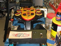
The new pack pack was designed this summer for my next cross country season using the backbone of a portable baby carrier as the base. Off of that I added an M D F (medium density fiberboard) faceplate that had hole cut to the sizes of the speakers (two 5" speakers and four 2" speakers) and was contoured to look nice and not catch on low hanging foliage. The faceplate was painted with matte black acryllic paint an was finished with 3 coats of clear gloss polyurethane. Next the speakers were added and screwed into place. The coverings for the 4 small speakers were made out of 3/16" aspen, I first cut the inside circle and drilled the pilot holes for the screws, I then contoured them, added a coat of polyurethane, painted the red trim on the inside, added more poly, and added the speaker mesh on the back salvaged from and old stereo system and screwed them into place. CAD drawings of the entire speaker assembly (excluding black mesh) can be found Here, they were drawn rather hastily so the dimensions and proportions won't be perfect but they give another good 3D representation of what the Pack looks like.
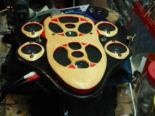
The covering for the middle speakers were made by designing the layout first then I cut out theholes around the middle support then I carved out the red parts, poly urethaned everything and painted the red parts. Next I soldered the connectionn on the speaker assembly then added the inputs on the faceplate, in a location that allowed the cable from the CD player/I Pod/MP3 player to run under neath the left arm to a special pocket on the left arm strap.

Below are more pictures taken during construction
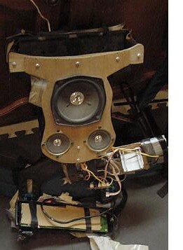
This picture was taken while the front speaker assmbly was off, during this time, I added the carrying strap and routed the wiring. I then added the waterproof nylon and foam backing that protects the wiring and speakers. (the backing was salvaged from an old back pack)
Not shown is the speaker assembly without the covering. Wired in mono, the power for the lower 3 speakers route through a toggle switch. Which obviously makes everything much louder. The other toggle switch interrupts the power wire that runs from the battery box at the top to the wooden box at the bottom and turns the whole contraption on and off.
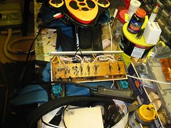
Shown here is the circuit board for the amplifier around wich I designed the lower black box. Inside was the original power button, however by adding the toggle directly to the power wire I can bypass the original switch. I can now permanantly leave this switch on (it is boxed in and inaccessible) and turn the power on and off from the new more convenient and cooler looking right toggle on the faceplate.
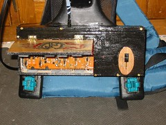
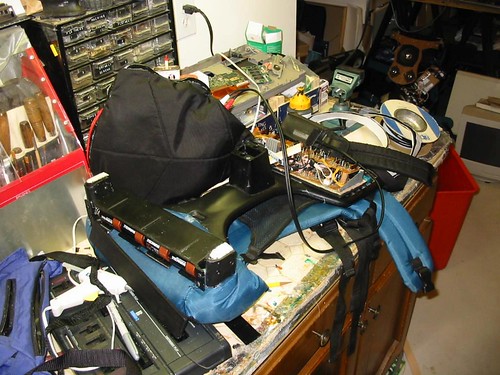
This is a picture of the completed amplifier housing. Notice the magnetic door that prevents tampering. the only control that is left in the open was the volume control (which goes to 11) for easy access. Not shown are the two 1/4 inch inputs at the bottom, and the input echo control also on the bottom wall of the box. below is a shot of the box with the lid closed.
Here, is shown the finished amp houseing without the poly urethane coat on it. Both it and the face plate were painted with the same acryllic basecoat of black and you can now see the dramatic difference between the two.
The covering for the battery box (shown in the fifth picture up) was made using 3/16" aspen, a length of nylon ripstop strapping, and velcro.
Although the finished product is still slightlty too heavy to run with effectivly, it is still quite loud and and it is much better looking, much more robust, and operates better then the prototype that I built with my brother two years ago. It runs conveniently off of 8 D batteries, which last for a good amount of time. The other cool fact is, because I left the microphone 1/4" inputs in proper functioning order, It is possible to plug one's guitar into the paxkpack and then proceed to travel wherever you wan't. The Back Pack also serves as a portable guitar amplifier and sound system that goes wherever you go.
Finally, views of the old, and new together.
Here is a link of the CAD drawings of the whole assembly
CAD
Front Page
Comments (0)
You don't have permission to comment on this page.